
Since I don’t really have space for a model rail layout, I tend to mess about with small model rail related projects. One of the aspects about model rail I genuinely enjoy is the automation side. Interfacing the physical with the digital world is a heck of a lot of fun. Using European Uhlenbrock equipment goes hand in hand with LocoNet.
 Loconet is part of a DCC train control system designed by Digitrax to control a model train layout. LocoNet is a Peer to Peer Local Area Network (LAN) designed for very high traffic capacity and free-form wiring as well as future system expandability and ease of upgrade. It is a separate circuit from the track power used to run model trains.
Digitrax developed LocoNet to handle the communications between throttles, stationary decoders, and other devices that need to communicate with the command station.
Digitrax works with companies that build LocoNet Compatible Products. This gives LocoNet users more choices in hardware & software for creating the layout you want. To be able to produce a LocoNet product you need a license from Digitrax. Fortunately for us, Digitrax also has a personal edition license.
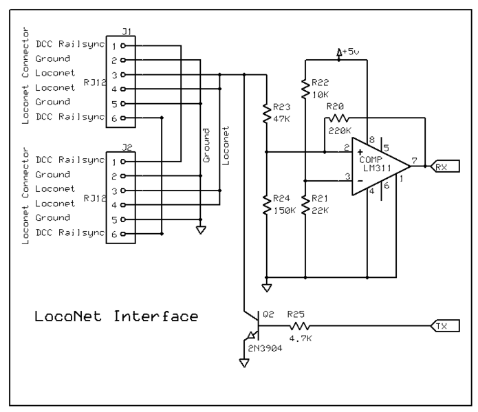 Interfacing an Arduino to LocoNet is quite simple using the Model Railroading with Arduino library. The hardware side of things isn’t rocket science either. But building it up on a breadboard, wires sticking out all over, gets old real fast.
I have two GCA185 LocoNet shields by Peter Giling. They work like a charm but the standard Arduino form factor is a bit too big for my taste.
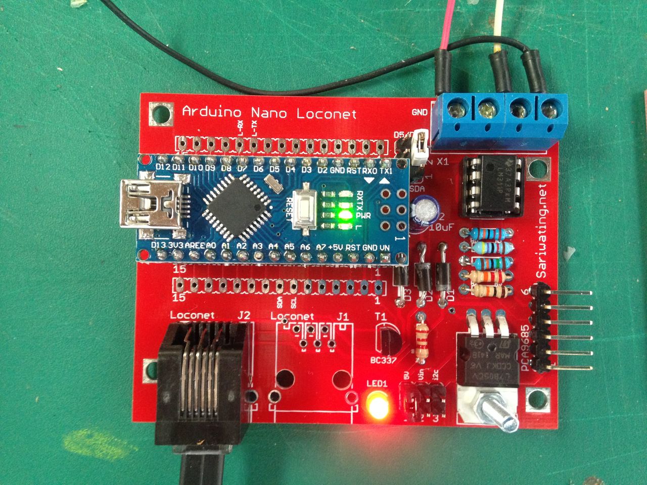
So using Eagle Cad I designed an interface print for the Arduino Nano. I discarded the D-SUB9 connectors and added i2c pull-up resistors. They are selectable by a jumper. This means that you can use this interface to connect to almost any i2c device. Think of an MCP23008 or MCP23016 for I/O, an OLED or LCD screen.
I also added a connector for a PCA9685. The PCA9685 is and i2c-controlled PWM driver with a built in clock. That means that, unlike the TLC5940 family, you do not need to continuously send it signal tying up your microcontroller, it’s completely free running!
 It is 5V compliant, which means you can control it from a 3.3V microcontroller and still safely drive up to 6V outputs (this is good for when you want to control white or blue LEDs with 3.4+ forward voltages)
6 address select pins so you can wire up to 62 of these on a single i2c bus, a total of 992 outputs – that’s a lot of servos or LEDs
I also made the i2c SDL/SCL swappable to D5 and D6 by setting jumpers. In the youtube below I have used this to connect a few WS2812b RGB LEDs to make some cheap signals. Perfect for usage in a sub level staging area.
 The LocoNet Interface PCB I designed.
 The blue connector for left to right: 5V – SCL/D5 – SDA/D6 – GND
 Looking good.
 WS2812b LEDs soldered together to make simple signals.
 Individually controllable for the Arduino.
https://www.youtube.com/watch?v=NwDb8vO_KEs
The code for the WS2812b simple signals is on my GitHub.
L.S.,
Is an layout and/or gerber file (EAGLE ?) available of this “The LocoNet Interface PCB” ? (latest version 1.x)
Regards and thanks in advance,
Theo.
It’s actually a nice and useful piece of info.
I am satisfied that you simply shared this helpful info
with us. Please stay us up to date like this. Thanks for
sharing.
Hello,
interesting work, thank you for sharing the code. Can you please share the schematics for the pcb and the breadbord?
Kind Regards
Andreas
Hi, can you make your gerber file for the nano loconet pcb available to download, please ?
The Eagle files are in the links with my new video. https://www.youtube.com/watch?v=EKkzLZpOJWU
Hello Timo,
Fantastic posts and loving the Arduino + LocoNET on your YouTube channel, would it be possible if you could give me an email?
Cheers
Des
Hello,
I had 10 of the version 2 pcb made. Can you please explain how to get the servo’s or led’s working on the PCA9685 ?
How do I trigger them using the loconet or DCC signal ?
You also mention the oled lcd. How do I get that working ?
Hi Timo,
Thanks for your lovely video on Arduino Loconet – I would like to get a circuit board made – please could you advise on what specification of board is required –
Number of layers and size so an idiot like me who has never had a circuit board printed before can tell a manufacturer what he wants…Many thanks
Just simple 2 layer design (top and bottom)
I’m going through here because I’m trying to understand your weather station files with DS2423 and DS2450 on github. I can not understand the use of sensors.h as libraries, without the use of .cpp files.
Yet your github is particularly interesting because as your KNX uses and a weather station like yours.
It would be super nice to put on the track …..
cordially
With an Arduino you don’t have to use a cpp file. You can if you want to and it’s better coding but it works with just putting all the code in the .h file.
So the sensors.h file for me was just a way to put the subroutines and functions for the sensors in its own location instead of in the ino.
The sensor.h file just call routines from the included libraries:
#include OneWire.h
#include DallasTemperature.h
#include DS2423.h
So you could just include those in your ino and use them directly from there.
But recently I made the switch to ESPhome because I’m running Home Assistant and that has really worked out for me in terms of time and stability of the sensors around the house.
Hi Timo,
Just completed your version 2 board of your Loconet Interface. I do have a couple of questions though.
1. I am having difficulty in locating the RJ12 sockets. The ones that I have (and seem the most common on ebay), have the pins located in a different position. Do you have a product code for the one’s that you used?
2. With reference to the LED’s I have placed them with the cathode (long wire) to the right when looking at the board from the RJ12 socket position. Is that correct?
I got them from AliExpress: Link
Absolutely awesome work Timo. As for the RJ11, US based friend can get it from Sparkfun: https://www.sparkfun.com/products/132
That is in fact the footprint used on the board.
I ordered my boards, as soon as they come I will start to play !!
Keep up this work, it is a very helpful endeavor for us model railroaders.
Happy New Year!